- Pressure Sensor, Pressure Transducer, Pressure Transmitter

- 2020-07-28
- Zhyq
- 21
Pressure Transmitter Installation Tips
When choosing a pressure transmitter for your application, a number of things have to be considered. Some of the common problems that our customers tend to have are to do with installation, output signals, pressure range, chemical compatibility, barometric pressure and drift.
Here are a few things to think about to help you avoid problems…
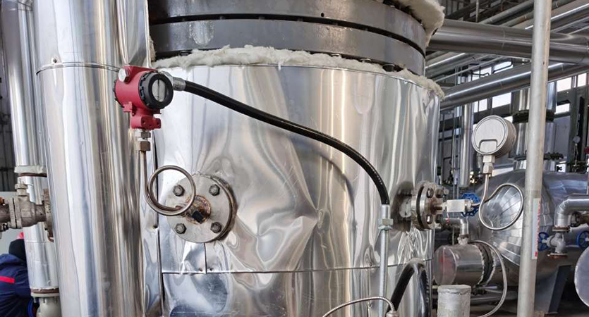
Installation
First and foremost, always install the pressure transmitter on systems which are in the unpressurized state. Pressure transmitters are generally rugged devices built to withstand the elements of the industrial world. Once installed, your pressure transmitter can be left alone with minimal need for attention. However, it is a precision measuring device and still requires a certain amount of care during installation to ensure trouble free performance and longevity.
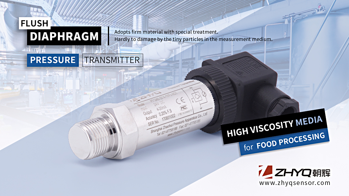
The process connection (or pressure fitting) on the transmitter is designed to snugly secure the unit in place. Firstly you must ensure that the process connection on the transmitter properly mates with your pressure port. ¼”BSP or NPT male threads are common.
During the installation process, ensure that the sealing surfaces on the device and the process are clean and free of damage. Only use the appropriate tool to screw the device in or unscrew it, and always tighten the transmitter to the manufacturers’ instructions to avoid the possibility of leaks. Take care not to over-tighten as this can result in incorrect readings during your tests, not to mention the possibility of damage to the thread which can result in leaks. Correct tightening will not harm the transmitters’ performance and will assure leak-proof operation.
All transmitters require two connections, a mechanical pressure connection and an electrical connection. Just as you would check the compatibility of the pressure connection, you should always check the electrical configuration of the transmitter before purchase. The electrical termination on a pressure transmitter usually has a multi-pin connector or a cable, so your process must have the same wiring code for electrical pin-to-pin compatibility. All electrical interconnections between system components should be clean and have the highest integrity. Ensure that adequate earthing is provided via the plug or the cable shield and make sure that no moisture can penetrate via the leads.
The electrical connector is usually the most vulnerable component of a pressure transmitter and care should be taken not to dent the connector shell or damage the pins. Damage like this can put the transmitter out of service completely. Many good quality transmitters have zero and span adjustment potentiometers (or access holes) located on the transmitters connector plate. It is always good to install the transmitter in such a way that the adjustments can be easily accessed with a screwdriver.
Wiring
The most common source of system error is the input wiring to the transmitter. This error is due to noise generated by electrostatic coupling and inductive pickup (EMI/RFI). Electrostatic coupling generates noise from coupling of the electric fields surrounding signal wires. To eliminate these unwanted signals, use shielded cable and ground only on one end of the shield.
Motors, power lines, transformers and similar energy sources generate electro-magnetic fields, which can be picked up inductively. These strong magnetic fields are a source of noise, which can cause signal errors. Twisting of the signal wires will help to cancel this noise. In those cases where a low signal level cable is close to high voltage cables, the low level cable can be run in a metal conduit. To help minimize grounding problems, a signal circuit should be grounded in one place only.
Outputs
When deciding which output you should choose for your pressure transmitter, you must look at what the whole application or process requires. For high temperature applications the mV output should be the first consideration. For industrial environments with potentially unregulated power supplies, the voltage outputs will suffice, and for applications where your signal needs to transmit over long distances then a 4-20mA transmitter is perfect.
mA output is certainly the most common signal in use in industrial processes. Varying from 0 or 4mA to 20mA, it is a two wire installation in which the power supply provides voltage to the transmitter and the transmitter controls the current in the circuit to generate the signal. A 4-20mA signal is least affected by electrical noise and resistance in the signal wires, so these transmitters are best used when the signal needs to travel across long distances.
Voltage output is a simple output method used in many processes. Voltage signals are usually 0-5V or 0-10V. They are vulnerable to electrical interference which can corrupt the signal, and voltage drops caused by wire resistance over longer distances.
Millivolt (or Ratiometric) outputs are common with unamplified sensors. The output signal is proportional to the input (or excitation voltage). Because the output signal is so low, the transducer should not be located in an electrically noisy environment and the distances between the transducer and readout instrument should be kept short. This type of output doesn’t have an amplifier incorporated into the design, so the transmitters tend to be more compact, and can handle harsher environments more easily than the other output types.
Pressure Range
Any pressure transmitter that you purchase will be calibrated to provide a specific electrical output for a specified pressure range. You must carefully consider the pressure range you’ll be working with and you will need to choose a sensor with capacity that closely fits that range. Choosing a sensor with a range much higher than you need will affect the accuracy of your measurement, while using a sensor with a pressure range too low introduces the risk of overload (or overpressure) causing the pressure diaphragm to burst.
A high pressure spike is the main cause of overpressure. Asudden change in momentum within the system or the release of stored pressure from valves opening and closing generate a tremendous amount of energy over a very short time period which can be verydifficult to detect and if they are allowed to reach adiaphragm that is not adequately protected they can cause irreparable damage. Therefore, the wise choice is to select a pressure range such that operating pressure is approximately 80% of full scale to avoid this problem.
Chemical Compatibility
What media will you be measuring and is it compatible with the material of your pressure transmitter? An important question!
Pressure transmitters are used to operate in a variety of media, so they need to have some built-in protection against hostile fluids and gases. These chemicals can attack the instruments both internally and externally, typically from leaks or fumes. Electronics and wiring may corrode which will often lead to failure of the pressure transmitter. The product exterior and internal electronics must therefore be protected from chemical exposure through good design and appropriate selection of materials of construction. So always consider whether the materials used in the construction of your selected pressure transmitter are suitable for use with the media in your process.
Barometric Pressure
Barometric pressure (also known as atmospheric pressure) is the force exerted by the atmosphere at a given point. It is known as the “weight of the air”. Fluctuations in barometric pressure are usually a sign of weather conditions and also vary with altitude and moisture.
It has a specific impact on sealed pressure sensors, including absolute and sealed types of pressure sensors, but doesn’t have any influence on vented pressure types such as gauge and vacuum pressure measurement.
The impact of barometric pressure is inversely proportional to the pressure range of the sensor meaning that it can significantly affect the accuracy in lower pressure ranges.
The unpredictable nature of barometric changes can make it very frustrating to technicians attempting to keep equipment in calibration. If changes in barometric pressure are resulting in inaccurate pressure measurement then the application should be examined to determine if a vented sensor could be used. A potential solution is to use a differential pressure transmitter. Measurements are recorded as the difference between two readings resulting in an output that is normalised to barometric pressure.
Drift
Have you ever wondered why your pressure transmitter performs well at first, but then slowly falls outside calibration? This is a problem known as “drift”. Pressure sensor drift is a gradual degradation of the sensor and other components that can make readings offset from the original calibration. Possible causes of this have been studied for years, but there is no single conclusive cause for the error. Regular re-calibration is a good way to keep on top of drift and regular “field zero readings” will help to eliminate the effects of drift on pressure transmitter readings.
So we’ve given you a few things to consider to ensure minimal fuss when installing and operating your pressure transmitter. Need more technical help? Then don’t hesitate to contact us.
Leave Your Inquiry
Your email address will not be published. Required fields are marked *